TechoflashamanMagnetism Circuit Diagram In this electronics project, I will show you a Magnetic field detector using Hall-effect sensor, where the detector indicates the presence and polarity of the magnetic field, whether it is a neodymium magnet, ring magnet, or disc magnet. The operating voltage for this detector range from DC 3.7 V to 12 V and current 300 mA to 800 mA.
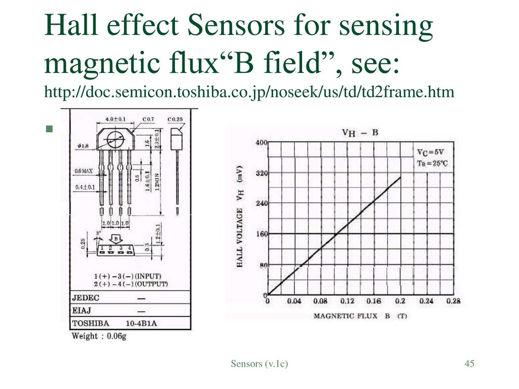
A Hall sensor is an electronic device that detects the presence and magnitude of magnetic fields. It operates on the principle of the Hall effect, which is the production of a voltage difference (Hall voltage) across an electrical conductor, transverse to an electric current in the conductor and a magnetic field perpendicular to the current.
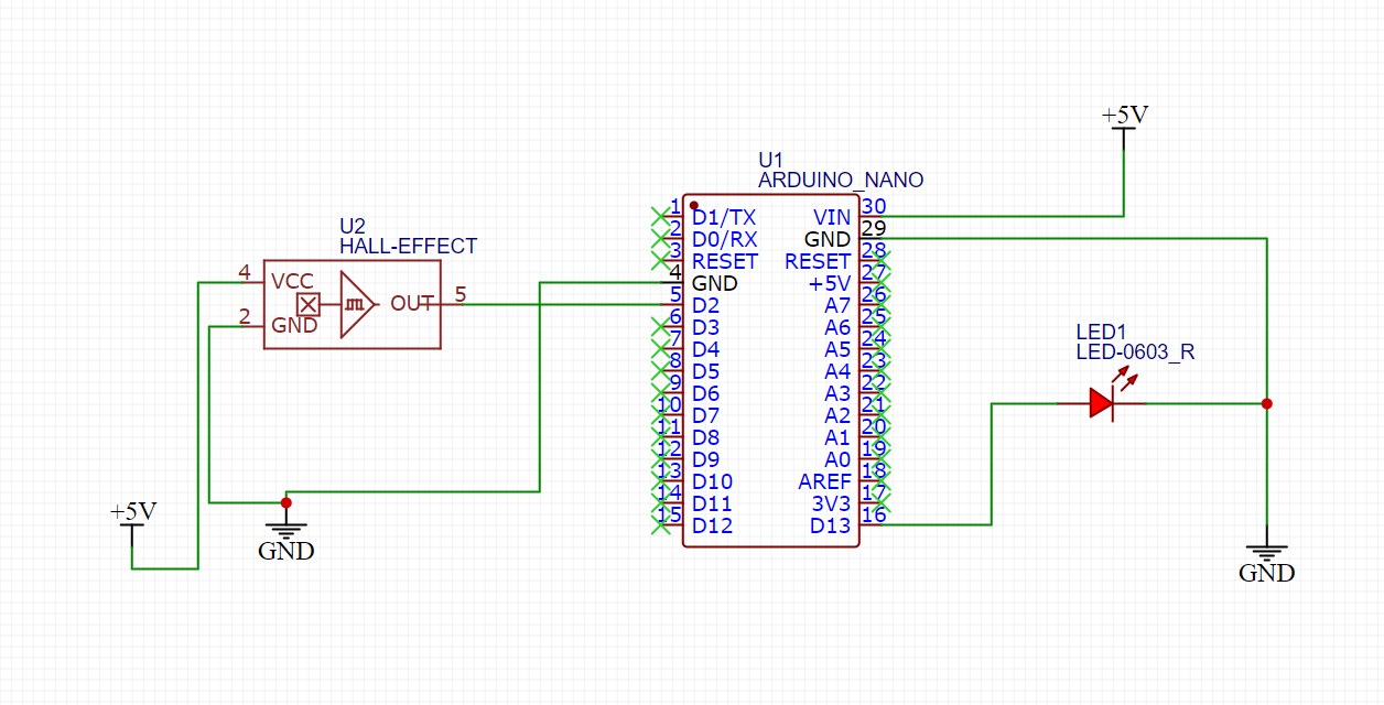
How to Use a Hall Effect Sensor With Arduino Circuit Diagram
What is Linear Hall-Effect Sensor: The hall-Effect sensor can be the easiest method to detect Magnetic fields in a region. There are many module ranging from the cheapest to the high-priced version of the Hall effect sensor. The version I'm using here is very basic and can be easily found in any online or offline store.

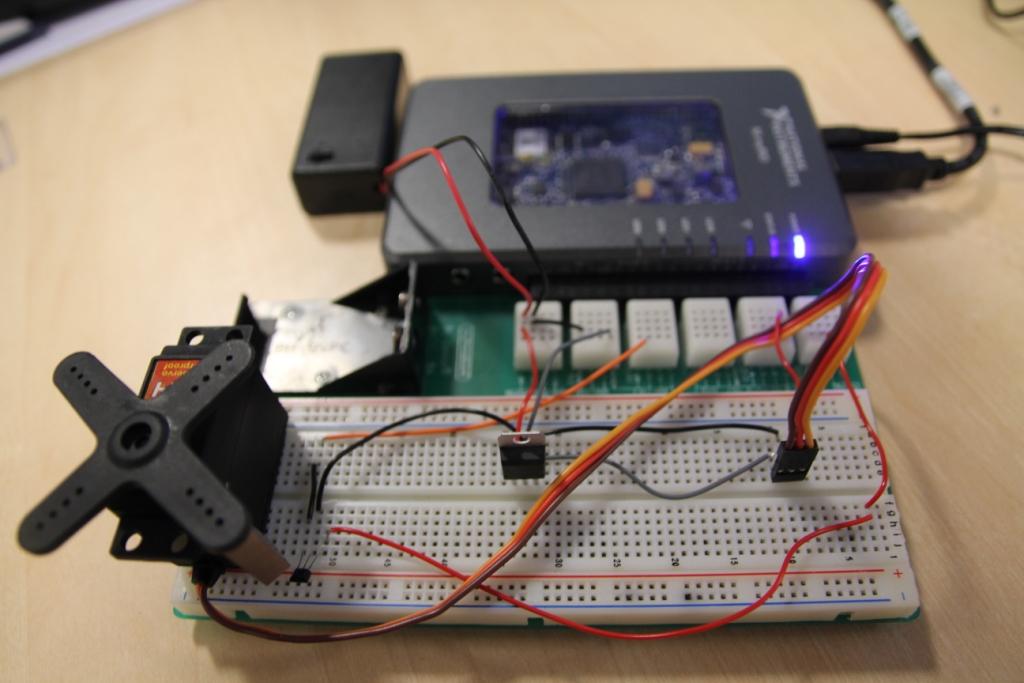
In this tutorial you learned how to use a hall effect sensor to detect magnetic fields and control an Arduino output. Hall effect sensors are very useful for proximity, position, and motion sensing. This is a basic example but demonstrates the core concept of using a hall effect sensor with an Arduino. There are many ways to expand on this
How to Measure Magnetic Fields with Hall Effect Sensor for ESP32 Circuit Diagram
The A3144 Hall sensor is not only versatile, but it also has a very reasonable price. affordable, making it ideal for both beginners and experts. Designed to measure magnetic fields y detect positionsIts ease of use and compact size make it an essential component in projects that require a device with no moving parts or with low mechanical wear.

5. How do you use hall effect sensors? To use Hall Effect sensors, you typically follow these steps: Connect the sensor to an appropriate power supply and ground; Position the sensor in the desired location to detect the magnetic field of interest; Read the sensor's output using an Arduino, microcontroller, or other measurement devices; The Hall effect sensor works on the principle of the Hall effect, which states that whenever a magnetic field is applied in a direction perpendicular to the flow of electric current in a conductor, a potential difference is induced. This voltage can be used to detect whether the sensor is in the proximity of a magnet or not.