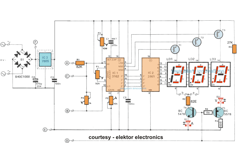
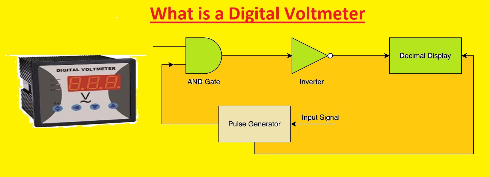
How to Make a Digital Voltmeter Ammeter Module Circuits Circuit Diagram Section 1: Understanding the Basics of a Digital Voltmeter Circuit. A digital voltmeter circuit is an essential tool for measuring voltage in electronic circuits. This section will provide an overview of the basic components and principles involved in building a digital voltmeter circuit. 1. Analog-to-Digital Converter (ADC) The heart of a However, an ICL7107 is a 3.5 digit ADC converter analog to digital, which devours low power. The IC has an internal circuit for driving four "seven-segment displays" to show that it is under measurement voltage. It likewise has a timer circuit and a reference voltage source.
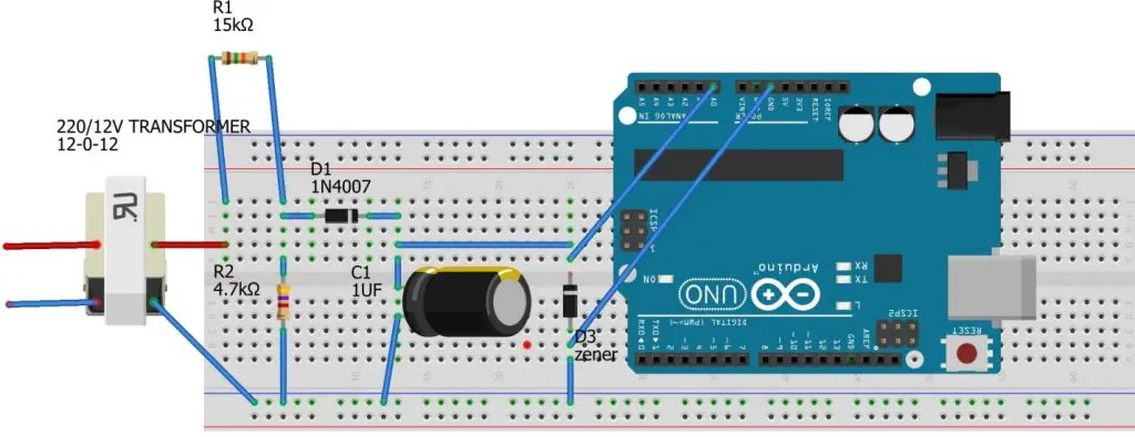
1. If you are interested in this circuit. You can apply to The digital capacitor meter project. 2. If you fear that it will not work. You can see the details of… Digital LED Voltmeter Kit. 3. You can look at the digital multimeter using ICL7107. 4. In the past, I used an old digital voltmeter circuit. But it was very old. You may not be able Figure 1 - Arduino Digital Voltmeter Circuit Diagram Figure 2 - Arduino Digital Voltmeter Circuit Diagram Components. Arduino UNO 16 x 2 Circuit Design. For measuring voltages less than or equal to 5V, first circuit can be used. For measuring voltages up to 50V, second circuit can be used.
Electronics Textbook Circuit Diagram
To get an effective voltmeter meter range in excess of 1/2 volt, we'll need to design a circuit allowing only a precise proportion of measured voltage to drop across the meter movement. This will extend the meter movement's range to higher voltages. Correspondingly, we will need to re-label the scale on the meter face to indicate its new The proposed digital voltmeter and ammeter circuit module can effectively be used alongside a power supply to indicate both voltage and current consumption by whatever load is connected through those attached modules. Now I can design this system in such a way that it can acquire concurrent voltage and current readings.
Digital Voltmeter Circuit Design using 8051 Microcontroller. In the above circuit, analog to digital converter IC data bits are connected to the PORT2. LCD data pins are connected to the POTR3 of controller and control pins RS and EN are connected to the P1.6 and P1.7 respectively. Working of this Digital Voltmeter Circuit is very simple. ADC inside the IC is integrating converter or Dual type Analog to digital converter. I have same design ckt of volt meter but the problem be is when I calibrate 5v =12.00 v the the meter reading will changes 0.10 v & it will slowly decresing reading , it's take 2 to 3 min for showing
